
Projects / Manufacturing Patterns

Project patterns for parts that combine casting, machining and assembly

These project pages describe the engineering sequence and the evidence that should be collected for a real case study.

Project engineering pattern Project engineering pattern
Housing
Sealing and bores
Thermal part
Fin and flatness
Enclosure
Fit and finish
Bracket
Stiffness and mounting
01 / Pattern

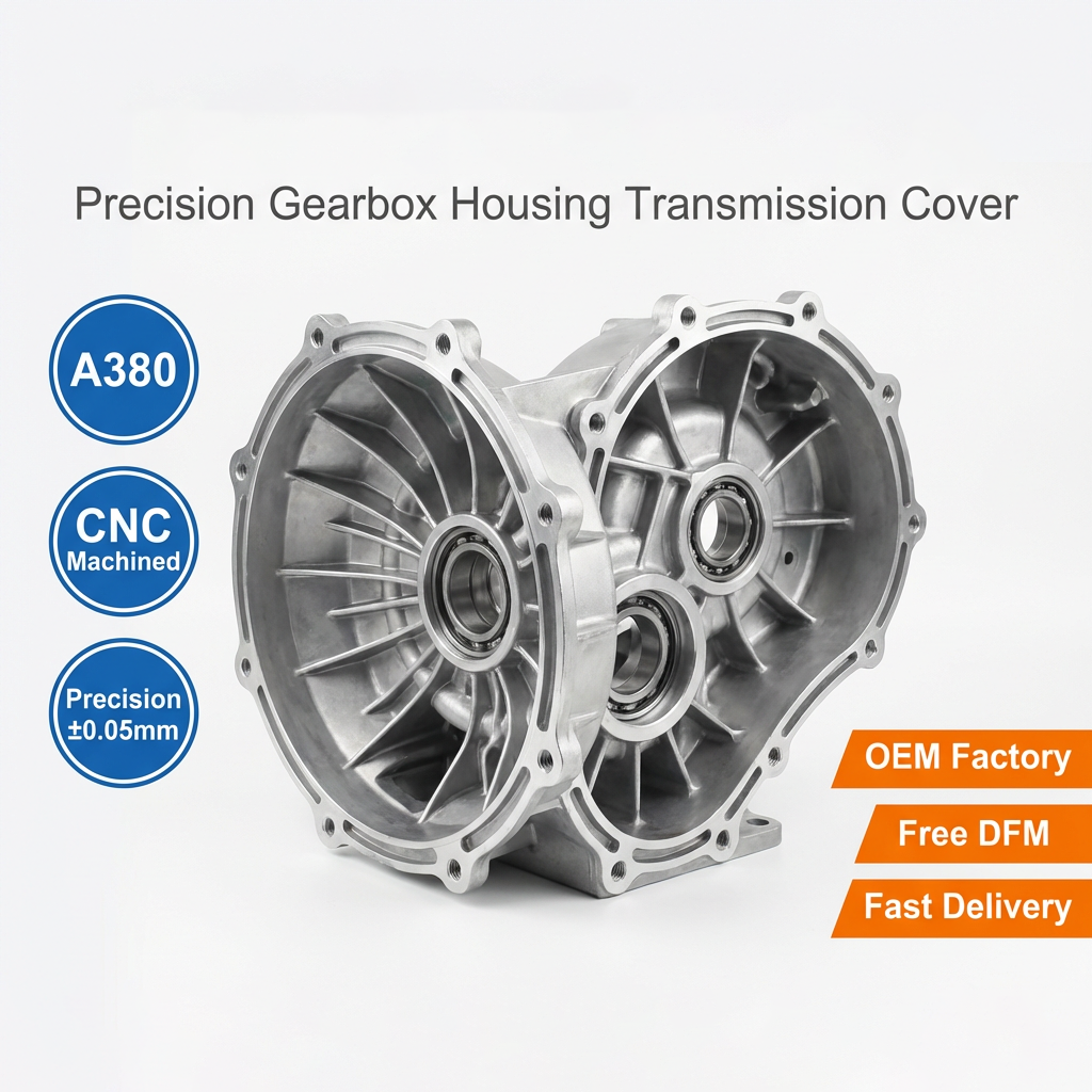
Gearbox housing project logic

A housing program connects wall and rib design, parting line, bearing bores, sealing surfaces and machining datums.

This page describes the project pattern only. It does not present an unnamed result, yield or customer claim as a completed case.

  • Material and process route
  • Tooling and sample review
  • CNC datum and bore strategy
  • Flatness, sealing and porosity controls
  • Inspection and release documents
02 / Pattern

Outdoor power enclosure project logic

A power enclosure adds environmental sealing, thermal behavior, mounting and finish requirements to the basic casting review.

  • IP target to be confirmed
  • Sealing and gasket interface
  • Powder coating and masking
  • Thermal path and mounting
  • Packaging and transport protection
03 / Pattern

LED heat sink project logic

A thermal part is judged by fin geometry, flatness, contact area, alloy behavior and finishing, not only by the external shape.

  • Alloy and thermal requirement
  • Fin and wall control
  • Flatness and mounting interface
  • Surface treatment
  • Dimensional and visual inspection
Evidence note

Real case studies require real project records.

Customer name, volume, yield, lead time, cost savings and quality results should only be published when the project owner approves the disclosure and the underlying record exists.

When those records are unavailable, the correct page type is a manufacturing pattern, not a fabricated case study.

Buyer questions

Questions to resolve before production.

These answers define the normal project path and the information needed for a useful quotation.

Provide the controlled 2D/3D drawing, material requirement, annual quantity, finishing requirement, critical dimensions, target market and delivery date.

An initial feasibility discussion is possible, but the quotation and tooling scope should be based on a controlled drawing revision.

Tolerance and inspection requirements are defined from the drawing, critical features, process capability and agreed datum strategy.

Ownership, storage, maintenance and transfer terms are defined in the quotation or supply agreement before the tooling project starts.

Related pages

Continue through the project path.

Use the internal links to connect the material, process, industry, product and RFQ pages around one project decision.

Send the drawing. Get the engineering questions first.

Include the material, annual quantity, finishing requirement, target market and delivery date. The review can start from STEP, IGS, DWG, DXF, PDF or ZIP files.

Start an RFQ
Upload drawing