
Requirement review
Confirm function, volume, material, finish, environment and delivery target.
A thermal component pattern for lighting products, with attention to fin geometry, flatness, finish and heat-dissipation requirements.
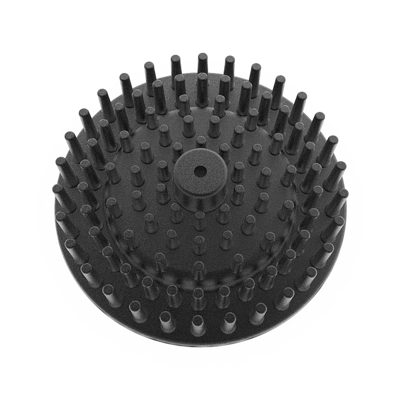 LED Heat Sink engineering pattern
A thermal component pattern for lighting products, with attention to fin geometry, flatness, finish and heat-dissipation requirements.
A useful product page starts with the functional requirement rather than the photo. The material, casting layout, machining datums, sealing surfaces, cosmetic zones and inspection plan should be defined from the part's use.
Use this table for project planning, then confirm every critical value against the approved drawing and process plan.
| Part family | LED Heat Sink |
|---|---|
| Manufacturing route | Die casting, tooling, CNC, finishing and assembly as required |
| Material | Aluminum, zinc or magnesium according to the application |
| Drawing inputs | STEP, IGS, STP, DWG, DXF, PDF and ZIP |
| Tolerance | ±0.05 mm as cast; ±0.01 mm on machined features |
| Inspection | Dimensional, material, functional and visual checks by drawing risk |
| Production data | Mold 15-25 days; T1 sample 3-5 days; production 7-15 days; 500,000+ pieces per month |
Each stage produces a decision or document that the next stage depends on. This keeps engineering, purchasing and production aligned.
Confirm function, volume, material, finish, environment and delivery target.
Review wall thickness, draft, ribs, parting, porosity risk, machining and sealing.
Build the tool, run T1 and approve the controlled sample.
Complete secondary operations, inspect and pack against the approved plan.
These answers define the normal project path and the information needed for a useful quotation.
Provide the controlled 2D/3D drawing, material requirement, annual quantity, finishing requirement, critical dimensions, target market and delivery date.
An initial feasibility discussion is possible, but the quotation and tooling scope should be based on a controlled drawing revision.
Tolerance and inspection requirements are defined from the drawing, critical features, process capability and agreed datum strategy.
Ownership, storage, maintenance and transfer terms are defined in the quotation or supply agreement before the tooling project starts.
Use the internal links to connect the material, process, industry, product and RFQ pages around one project decision.
Include the material, annual quantity, finishing requirement, target market and delivery date. The review can start from STEP, IGS, DWG, DXF, PDF or ZIP files.